BootLogo
Bootlog is used to display pictures when uboot starts. It can display pictures within 2 seconds when the board is powered on. The following describes the implementation process of bootlog on ssd20x platform. By default, we have learned about the generation of rootfs in Chapter 4.
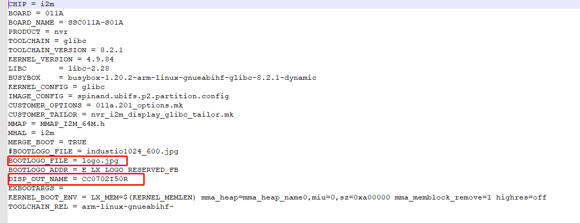
# vi project/configs/nvr/i2m/8.2.1/spinand.glibc.011a.64(201)
# vi project/configs/nvr/i2m/8.2.1/spinand.glibc.011a.128(202)

Will logo.jpg Copy to project/board/ini/misc/ Directory:
According to Chapter 10, adjust the screen reference and obtain the screen reference header file CC0702I50R_1024x600.h, but this screen parameter is suitable for MI architecture. Bootlog uses MHAL architecture, so it is necessary to change MI architecture to MHAL architecture

MhalPnlParamConfig_t stPanel_CC0702I50R =
{
    "CC0702I50R_1024X600", // const char *m_pPanelName;                ///<  PanelName
#if !defined (__aarch64__)
    0,
#endif
    0, //MS_U8 m_bPanelDither :1;                 ///<  PANEL_DITHER, keep the setting
    E_MHAL_PNL_LINK_TTL, //MHAL_DISP_ApiPnlLinkType_e m_ePanelLinkType   :4;  ///<  PANEL_LINK

    ///////////////////////////////////////////////
    // Board related setting
    ///////////////////////////////////////////////
    1,  //MS_U8 m_bPanelDualPort  :1;              ///<  VOP_21[8], MOD_4A[1],    PANEL_DUAL_PORT, refer to m_bPanelDoubleClk
    0,  //MS_U8 m_bPanelSwapPort  :1;              ///<  MOD_4A[0],               PANEL_SWAP_PORT, refer to "LVDS output app note" A/B channel swap
    0,  //MS_U8 m_bPanelSwapOdd_ML    :1;          ///<  PANEL_SWAP_ODD_ML
    0,  //MS_U8 m_bPanelSwapEven_ML   :1;          ///<  PANEL_SWAP_EVEN_ML
    0,  //MS_U8 m_bPanelSwapOdd_RB    :1;          ///<  PANEL_SWAP_ODD_RB
    0,  //MS_U8 m_bPanelSwapEven_RB   :1;          ///<  PANEL_SWAP_EVEN_RB

    0,  //MS_U8 m_bPanelSwapLVDS_POL  :1;          ///<  MOD_40[5], PANEL_SWAP_LVDS_POL, for differential P/N swap
    0,  //MS_U8 m_bPanelSwapLVDS_CH   :1;          ///<  MOD_40[6], PANEL_SWAP_LVDS_CH, for pair swap
    0,  //MS_U8 m_bPanelPDP10BIT      :1;          ///<  MOD_40[3], PANEL_PDP_10BIT ,for pair swap
    1,  //MS_U8 m_bPanelLVDS_TI_MODE  :1;          ///<  MOD_40[2], PANEL_LVDS_TI_MODE, refer to "LVDS output app note"

    ///////////////////////////////////////////////
    // For TTL Only
    ///////////////////////////////////////////////
    0,  //MS_U8 m_ucPanelDCLKDelay;                ///<  PANEL_DCLK_DELAY
    0,  //MS_U8 m_bPanelInvDCLK   :1;              ///<  MOD_4A[4],                   PANEL_INV_DCLK
    0,  //MS_U8 m_bPanelInvDE     :1;              ///<  MOD_4A[2],                   PANEL_INV_DE
    0,  //MS_U8 m_bPanelInvHSync  :1;              ///<  MOD_4A[12],                  PANEL_INV_HSYNC
    0,  //MS_U8 m_bPanelInvVSync  :1;              ///<  MOD_4A[3],                   PANEL_INV_VSYNC

    ///////////////////////////////////////////////
    // Output driving current setting
    ///////////////////////////////////////////////
    // driving current setting (0x00=4mA, 0x01=6mA, 0x02=8mA, 0x03=12mA)
    1,  //MS_U8 m_ucPanelDCKLCurrent;              ///<  define PANEL_DCLK_CURRENT
    1,  //MS_U8 m_ucPanelDECurrent;                ///<  define PANEL_DE_CURRENT
    1,  //MS_U8 m_ucPanelODDDataCurrent;           ///<  define PANEL_ODD_DATA_CURRENT
    1,  //MS_U8 m_ucPanelEvenDataCurrent;          ///<  define PANEL_EVEN_DATA_CURRENT

    ///////////////////////////////////////////////
    // panel on/off timing
    ///////////////////////////////////////////////
    30,  //MS_U16 m_wPanelOnTiming1;                ///<  time between panel & data while turn on power
    400,  //MS_U16 m_wPanelOnTiming2;                ///<  time between data & back light while turn on power
    80,  //MS_U16 m_wPanelOffTiming1;               ///<  time between back light & data while turn off power
    30,  //MS_U16 m_wPanelOffTiming2;               ///<  time between data & panel while turn off power

    ///////////////////////////////////////////////
    // panel timing spec.
    ///////////////////////////////////////////////
    // sync related
    70,  //MS_U8 m_ucPanelHSyncWidth;               ///<  VOP_01[7:0], PANEL_HSYNC_WIDTH
    160,  //MS_U8 m_ucPanelHSyncBackPorch;           ///<  PANEL_HSYNC_BACK_PORCH, no register setting, provide value for query only

                                             ///<  not support Manuel VSync Start/End now
                                             ///<  VOP_02[10:0] VSync start = Vtt - VBackPorch - VSyncWidth
                                             ///<  VOP_03[10:0] VSync end = Vtt - VBackPorch
    10,  //MS_U8 m_ucPanelVSyncWidth;               ///<  define PANEL_VSYNC_WIDTH
    23,  //MS_U8 m_ucPanelVBackPorch;               ///<  define PANEL_VSYNC_BACK_PORCH

    // DE related
    230,  //MS_U16 m_wPanelHStart;                   ///<  VOP_04[11:0], PANEL_HSTART, DE H Start (PANEL_HSYNC_WIDTH + PANEL_HSYNC_BACK_PORCH)
    33,  //MS_U16 m_wPanelVStart;                   ///<  VOP_06[11:0], PANEL_VSTART, DE V Start
    1024,  //MS_U16 m_wPanelWidth;                    ///< PANEL_WIDTH, DE width (VOP_05[11:0] = HEnd = HStart + Width - 1)
    600,  //MS_U16 m_wPanelHeight;                   ///< PANEL_HEIGHT, DE height (VOP_07[11:0], = Vend = VStart + Height - 1)

    // DClk related
    1344,  //MS_U16 m_wPanelMaxHTotal;                ///<  PANEL_MAX_HTOTAL. Reserved for future using.
    1344,  //MS_U16 m_wPanelHTotal;                   ///<  VOP_0C[11:0], PANEL_HTOTAL
    1344,  //MS_U16 m_wPanelMinHTotal;                ///<  PANEL_MIN_HTOTAL. Reserved for future using.

    635,  //MS_U16 m_wPanelMaxVTotal;                ///<  PANEL_MAX_VTOTAL. Reserved for future using.
    635,  //MS_U16 m_wPanelVTotal;                   ///<  VOP_0D[11:0], PANEL_VTOTAL
    635,  //MS_U16 m_wPanelMinVTotal;                ///<  PANEL_MIN_VTOTAL. Reserved for future using.

    51,  //MS_U8 m_dwPanelMaxDCLK;                  ///<  PANEL_MAX_DCLK. Reserved for future using.
    51,  //MS_U8 m_dwPanelDCLK;                     ///<  LPLL_0F[23:0], PANEL_DCLK          ,{0x3100_10[7:0], 0x3100_0F[15:0]}
    51,  //MS_U8 m_dwPanelMinDCLK;                  ///<  PANEL_MIN_DCLK. Reserved for future using.
                                             ///<  spread spectrum
    25,  //MS_U16 m_wSpreadSpectrumStep;            ///<  move to board define, no use now.
    192,  //MS_U16 m_wSpreadSpectrumSpan;            ///<  move to board define, no use now.

    160,  //MS_U8 m_ucDimmingCtl;                    ///<  Initial Dimming Value
    255,  //MS_U8 m_ucMaxPWMVal;                     ///<  Max Dimming Value
    80,  //MS_U8 m_ucMinPWMVal;                     ///<  Min Dimming Value

    0,  //MS_U8 m_bPanelDeinterMode   :1;          ///<  define PANEL_DEINTER_MODE,  no use now
    E_MHAL_PNL_ASPECT_RATIO_WIDE,  //MHAL_DISP_PnlAspectRatio_e m_ucPanelAspectRatio; ///<  Panel Aspect Ratio, provide information to upper layer application for aspect ratio setting.
  /*
    *
    * Board related params
    *
    *  If a board ( like BD_MST064C_D01A_S ) swap LVDS TX polarity
    *    : This polarity swap value =
    *      (LVDS_PN_SWAP_H<<8) | LVDS_PN_SWAP_L from board define,
    *  Otherwise
    *    : The value shall set to 0.
    */
    0,  //MS_U16 m_u16LVDSTxSwapValue;
    E_MHAL_PNL_TI_8BIT_MODE,  //MHAL_DISP_ApiPnlTiBitMode_e m_ucTiBitMode;                         ///< MOD_4B[1:0], refer to "LVDS output app note"
    E_MHAL_PNL_OUTPUT_8BIT_MODE,  //MHAL_DISP_ApiPnlOutPutFormatBitMode_e m_ucOutputFormatBitMode;

    3,  //MS_U8 m_bPanelSwapOdd_RG    :1;          ///<  define PANEL_SWAP_ODD_RG
    2,  //MS_U8 m_bPanelSwapEven_RG   :1;          ///<  define PANEL_SWAP_EVEN_RG
    1,  //MS_U8 m_bPanelSwapOdd_GB    :1;          ///<  define PANEL_SWAP_ODD_GB
    0,  //MS_U8 m_bPanelSwapEven_GB   :1;          ///<  define PANEL_SWAP_EVEN_GB

    /**
    *  Others
    */
    1,  //MS_U8 m_bPanelDoubleClk     :1;             ///<  LPLL_03[7], define Double Clock ,LVDS dual mode
    0x001c848e,  //MS_U32 m_dwPanelMaxSET;                     ///<  define PANEL_MAX_SET
    0x0018eb59,  //MS_U32 m_dwPanelMinSET;                     ///<  define PANEL_MIN_SET
    E_MHAL_PNL_CHG_VTOTAL,  //MHAL_DISP_ApiPnlOutTimingMode_e m_ucOutTimingMode;   ///<Define which panel output timing change mode is used to change VFreq for same panel
    0,  //MS_U8 m_bPanelNoiseDith     :1;             ///<  PAFRC mixed with noise dither disable
    E_MHAL_PNL_CH_SWAP_0,
    E_MHAL_PNL_CH_SWAP_1,
    E_MHAL_PNL_CH_SWAP_2,
    E_MHAL_PNL_CH_SWAP_3,
    E_MHAL_PNL_CH_SWAP_4,
};


MhalPnlMipiDsiConfig_t stMipiDsiConfig_stPanel_CC0702I50R =
{

};
Will screen and header files CC0702I50R_1024x600.h a copy to the project/image/makefiletools/SRC/rawgenerator/pnl directory:
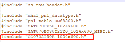
Modify disp_data_main.c
# vi project/image/makefiletools/src/rawgenerator/disp_data_main.cInclude the screen reference header file in it:
Add screen reference to sttable []:
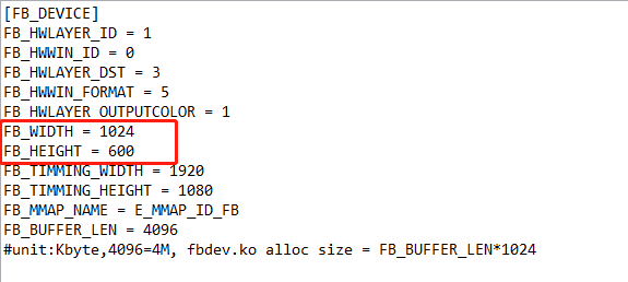
Modify screen resolution configuration
# vi project/board/i2m/SSC011A-S01A/config/fbdev.ini
After the modification, recompile the system image and update it to the board to observe the effect
# cd project/image/makefiletools/src/rawgenerator
# make
# cd -
# ./Release_to_customer.sh -f nand -p ssd201
