Chapter 16 PWM configuration
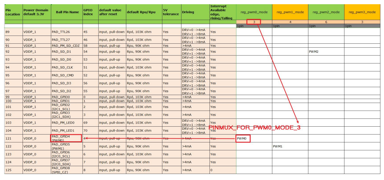
The SSD201 and SSD202 have a 4-way hardware PWM.The number is PWM0-PWM3, the output GPIO can be configured via Infinity2M-SSC011A-S01A-PADMUX-XXX. DTSI, adjust the PWM backlight, need to shield 4 GPIO:
#<PAD_GPIO4         PINMUX_FOR_PWM0_MODE_3         MDRV_PUSE_PWM0 >,
#<PAD_GPIO5         PINMUX_FOR_PWM1_MODE_4         MDRV_PUSE_PWM1 >,
#<PAD_GPIO6         PINMUX_FOR_EJ_MODE_3           MDRV_PUSE_EJ_TDO >,
#<PAD_GPIO7         PINMUX_FOR_EJ_MODE_3           MDRV_PUSE_EJ_TDI >,
For the second parameter, it is MODE_X according to SSD201HWCHECKLISTV6.XLSX [GPIOLIST] :

Then modify the PWM node of infinity2m-ssc011a-s01a-display.dtsi:
        pwm {
            compatible = "sstar,infinity-pwm";
            reg = <0x1F003400 0x600>;
            clocks = <&CLK_xtali_12m>;
            npwm = <2>;
            pad-ctrl = <PAD_GPIO4 PAD_GPIO5>;
            status = "ok";
        };
Where, NPWM indicates how many PWMS are used, and pad-ctrl indicates the binding pin. For example, here, PWM0 is bound to PAD_GPIO4, and PWM1 is bound to PAD_GPIO5.
The kernel needs to load the PWM driver:
# cd kernel
# ARCH=arm make menuconfig
When the system starts, you should see the /sys/class/ PWM /pwmchip0 directory.
Here is an example of the operation PWM1:
# cd /sys/class/pwm/pwmchip0
# echo 1 > export         According to the output
# cd pwm1
# echo 2000 > period      Represents the PWM wave of a 2kHz frequency
# echo 25 > duty_cycle    That means the duty cycle is 25%
# echo 1 > enable         Said can make
# echo 0 > enable         Said can make
文档更新时间: 2021-10-08 10:46 作者:Aeeditor
